The life of a plastic part begins with the digital handoff to a manufacturing supplier. This phase is fraught with hidden pitfalls, beginning with the very format of the files shared.
When submitting designs for a tooling quote and DFM (Design for Manufacturing) review, the default industry standard is typically the STEP (.stp) file.
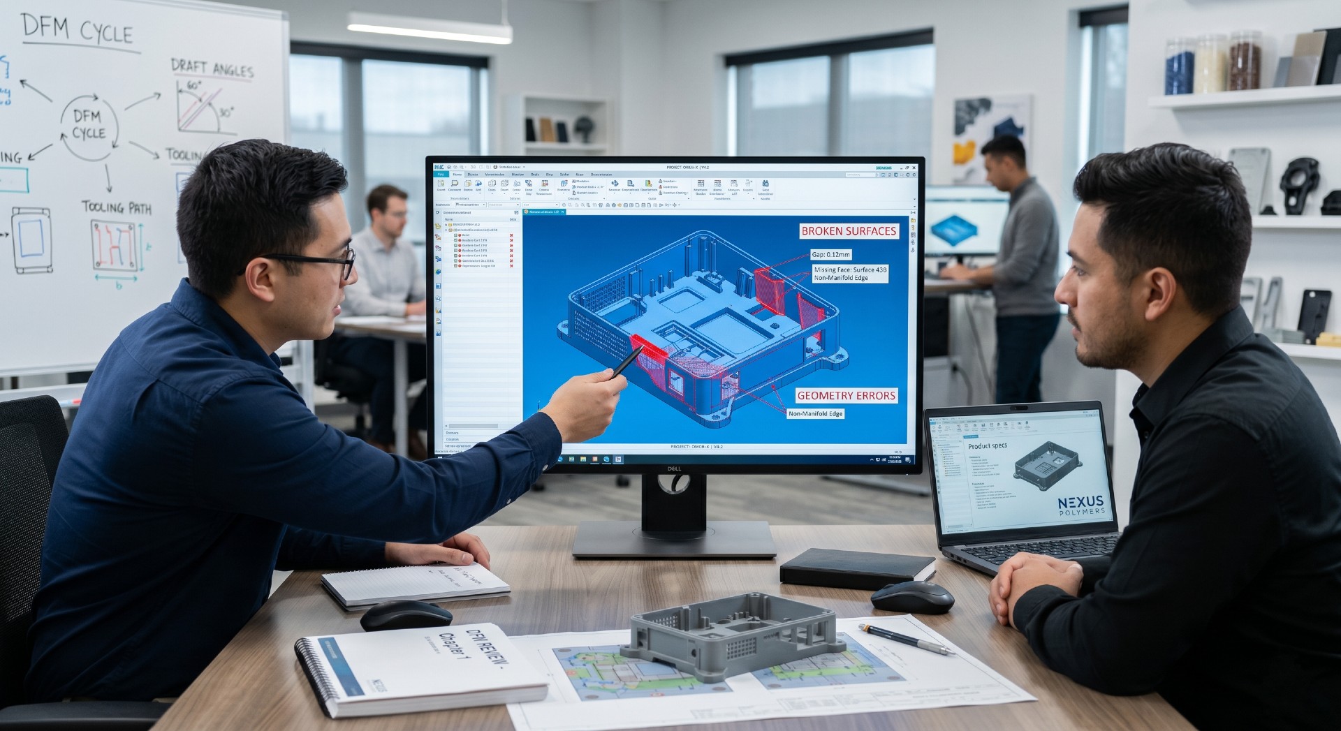
The B-Rep Translation Trap: STEP vs. Parasolid
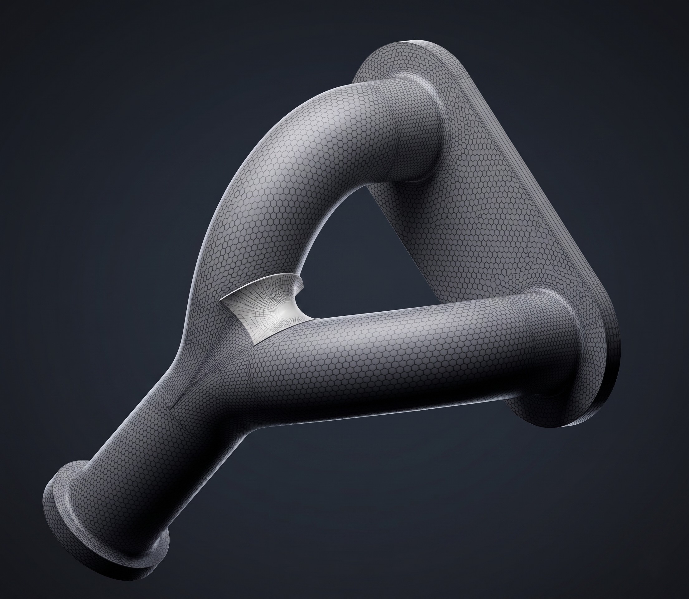
STEP is a highly versatile, neutral boundary representation (B-rep) format universally accepted across nearly all CAD and CAM platforms. However, transferring complex surface geometries via neutral formats can introduce microscopic translation defects—or, in the worst cases, totally broken surfaces.
The Parasolid Advantage
For engineers utilizing high-end parametric modeling software like SolidWorks, Siemens NX, or Solid Edge, exporting directly to a Parasolid format (.x_t or .x_b) is a superior, professional shortcut. Since these platforms natively operate on the Parasolid geometric modeling kernel, exporting in this format preserves absolute mathematical fidelity.
It eliminates the microscopic gaps between surfaces or misaligned face normals that often occur when a supplier's software misinterprets a STEP file. Furthermore, Parasolid files offer superior compression, yielding significantly smaller file sizes for complex assemblies—often removing the need to zip files entirely.
Pro Tip: If you are using Fusion 360 and have implemented complex surfaces into your model, moving to Parasolid is even more critical to ensure your geometry survives the trip to the supplier.
Avoiding the "Rebuild" Mismatch
When surfaces break during translation, the supplier is forced to rebuild them manually. This introduces a dangerous variable: the rebuilt geometry may not perfectly match your original design intent, leading to dimensional discrepancies in the final tool.
The "Cosmetic Thread" Warning
One of the most common causes of file corruption is the inclusion of cosmetic threads within a 3D file.
- The Problem: In 90% of cases, when a file containing cosmetic threads is translated from STEP to another CAD environment, the surfaces around the hole break. The model loses its "solid" status, turning into a collection of unknitted surfaces.
- 💡 The Solution: Export your 3D model with "clean," standard holes. Instead of modeling the thread, provide a 2D technical drawing alongside the 3D file that clearly specifies the required thread dimensions and tolerances.
The DFM Feedback Loop
Nowadays, nearly every supplier provides rapid DFM feedback during the initial quoting phase. At this stage, the feedback is often a formality, covering high-level concepts such as the number of cavities in the tool, basic and clear slider requirements, and the projected cost per part.
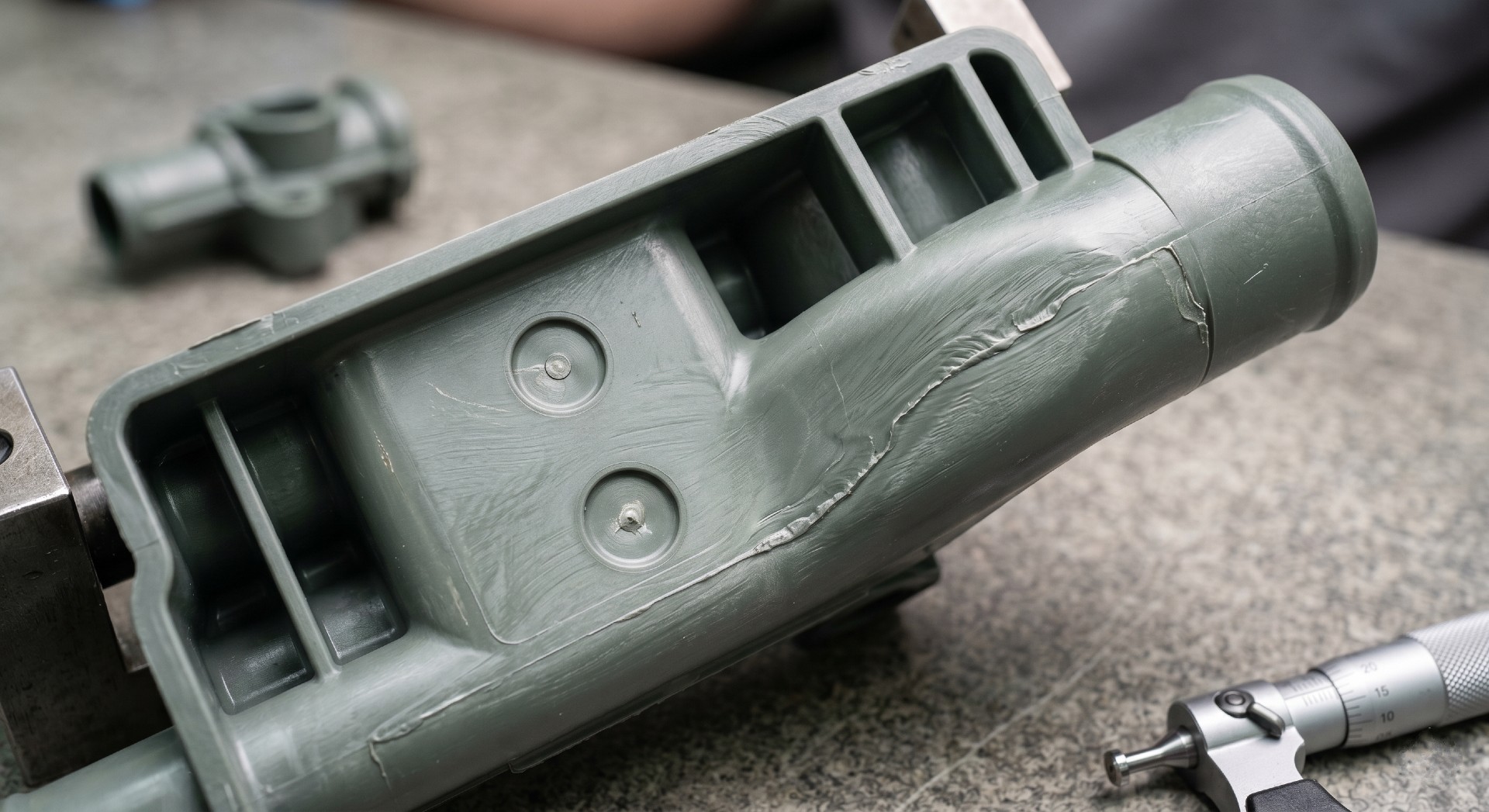
However, once the price is accepted and the Purchase Order (PO) is placed, the critical negotiation begins. A thorough, proper DFM review identifies catastrophic risks before a single chip of steel is cut. This phase can involve weeks of detailed discussions regarding uneven wall thickness, sink marks, and hidden undercuts.
In addition to these common issues, your engineering team and the supplier must achieve total alignment on the following:
1. Gate Placement and Flow Dynamics
The supplier will run mold flow simulations to dictate gate locations. The primary goals are:
- Preventing Jetting: Avoiding a high-velocity melt front that "shoots" into a thick section, which creates a visible, snake-like defect.
- Managing Weld Lines (Knit Lines): Strategically placing the areas where flow fronts meet so they fall in regions of low structural stress and minimal cosmetic importance.
2. Ejector Pin Layout
Pin placement is a negotiation to ensure the part can be pushed off the core without punching through the plastic or leaving unacceptable "witness marks."
💡 Pro Tip: Explicitly tell the supplier which surfaces are "Class A" (visible to the end user) before they start the layout. This prevents them from placing pins on cosmetic faces and saves days of back-and-forth.
3. Parting Lines and Draft Angles
The parting line is the division between the two sides of the tool. To ensure a clean release:
- Draft Requirements: Every surface must be drafted. While a bare minimum of 0.5° is sometimes used when space is tight, 1° is highly recommended for standard production.
- Geometry Warning: Never place a parting line on a rounded edge or "round." This is a recipe for flash (excess plastic) that is difficult to trim and looks unprofessional.
The Cost of Procrastination
Modifying a draft angle, moving a parting line, or thickening a wall takes minutes in CAD. While these changes might occasionally challenge the functionality of an assembly, making those same modifications after the tool steel is hardened can take weeks and cost thousands of dollars.
Ensure that you and your supplier have a complete mutual understanding and that every "check box" is marked before authorizing tool production.
By managing the "Digital Handoff" with these technical nuances in mind, you ensure the "DFM Dance" starts on the right foot—with a solid model and a clear path to production.