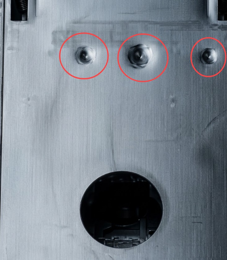
The structural architecture of a plastic part requires a radically different approach than machining metal. In injection molding, excessive mass is a profound liability. The thermodynamics of polymer cooling dictate that thick cross-sections cool at a much slower rate than thin sections.
When a design features a massive, thick block of plastic, the outer boundary touching the chilled steel mold solidifies almost instantly, forming a rigid skin. However, the internal thermal core remains molten. As this center eventually cools, it undergoes volumetric shrinkage. Because the outer skin is already cooled and crystallized, the shrinking core physically pulls the skin inward. The result is a "sink mark", a highly visible, structural depression on the surface of the part.
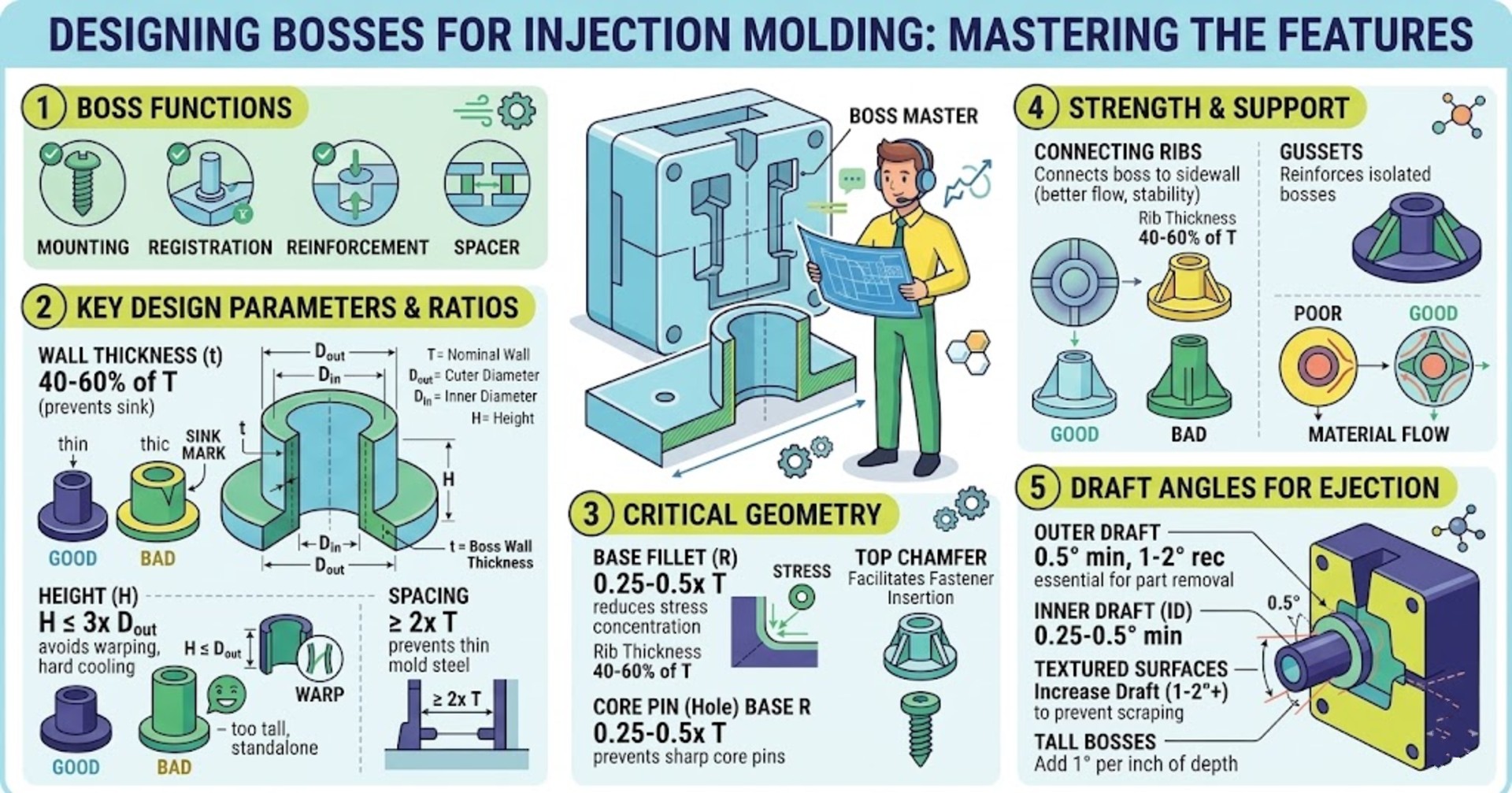
The 40-60% Rule for Boss Design
Bosses are cylindrical protrusions designed to accept threaded inserts, self-tapping screws, or alignment pins. A common pitfall in the design is creating excessively thick boss walls in an attempt to maximize thread pull-out strength.
To prevent sink marks on the opposite cosmetic face of the part, the wall thickness of a boss must be strictly maintained between 40% and 60% of the part's nominal wall thickness (or 0.5 to 0.7 times the product wall thickness). Exceeding 60% guarantees a localized thermal mass at the junction of the boss and the main wall, inviting severe sink marks and internal voids.
⚠️ Material Consideration: For materials with inherently high shrinkage rates, such as Polyethylene (PE) or Polypropylene (PP), boss walls may need to be engineered on the thinner end of that spectrum as they are more prone to shrinkage due to melting speed.
Beyond wall thickness, boss design is dictated by strict geometric ratios:
- Height-to-Diameter Ratio: A boss should never exceed a height of 3 times its outer diameter (OD). Excessively tall bosses require incredibly long, fragile core pins inside the mold. During the high-pressure injection phase, the advancing wave of viscous polymer can permanently bend or snap these core pins. Furthermore, deep blind holes create vacuum traps; if they are not vented via specialized pins, the trapped air compresses, superheats, and burns the plastic (a defect known as dieseling).
- Outer Diameter Sizing: The OD of the boss should be 2.0 to 2.5 times the major diameter of the screw it houses, providing a balance of hoop-stress resistance without creating a thermal mass.
- Fastener Engagement: The internal bore depth must be calculated to allow for at least 60% thread engagement with the incoming fastener.
- Spacing Metrics: Multiple bosses must be spaced at least 2 times the nominal wall thickness apart. Placing them too close forces the toolmaker to create razor-thin blades of tool steel between the cavities. These thin steel sections cannot accommodate internal cooling channels, causing them to overheat, fatigue, and ultimately crack during the molding cycle.
- Stress Relief Radii: Sharp internal corners act as stress concentrators where crack propagation begins. A fillet radius of 0.25 to 0.5 times the nominal wall thickness must be added at the base where the boss intersects the nominal wall.
⚖️ Boss Design: Do's & Don'ts
Ribs and Gussets
When a boss requires greater lateral strength, the solution is never to thicken the boss wall. Instead, the savvy engineer deploys ribs and gussets to tie the boss into adjacent sidewalls. Ribs act as structural I-beams, dramatically increasing the area moment of inertia without adding massive volume.
Just like bosses, ribs must adhere to the 40-60% thickness rule at their base. A critical DFM check involves evaluating the intersection where a rib meets a boss. The geometry must be carefully trimmed or radiused to ensure no thick, un-coolable section is left at the confluence of the two features.
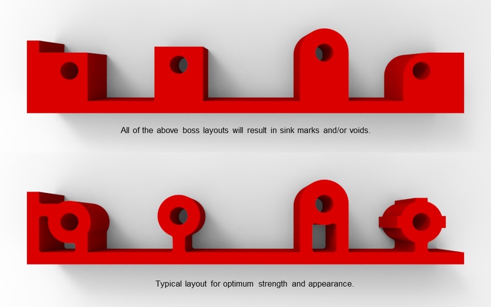
Thick Areas and Uneven Designs
Uneven wall thicknesses in a plastic part are a primary catalyst for molding defects. When plastic transitions abruptly from a thin to a thick cross-section, the difference in cooling rates causes the thick area to shrink more and pull on the surrounding material. This not only creates severe sink marks on cosmetic surfaces but also introduces molded-in stress that can warp the entire part.
To solve this, designers employ a technique known as coring out. Coring out involves removing excess material from thick sections to maintain a uniform wall thickness throughout the part. Instead of a solid block of plastic, the area is hollowed out, leaving structural ribs behind to maintain strength without the thermal mass penalty.
When transitions between different thicknesses are absolutely unavoidable, they should never be abrupt. A gradual transition—typically using a chamfer or a large radius over a length of at least 3 times the thickness difference—allows the plastic to flow smoothly and cool more evenly, mitigating stress and minimizing surface defects.
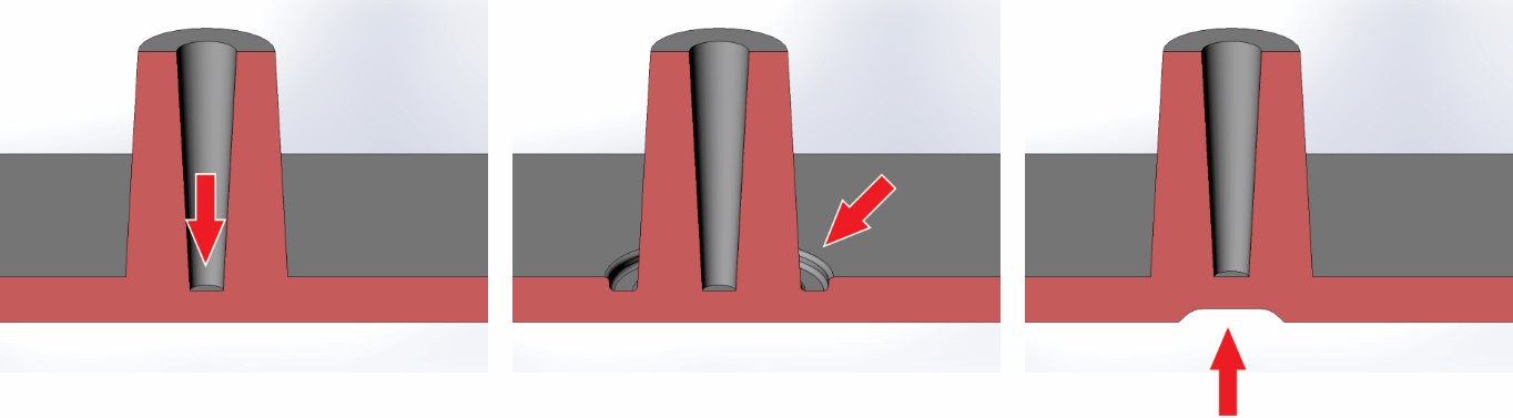
💡 Master Trick: Core-Out Around Bosses
My master trick to avoid sink marks around bosses is to "perforate" or core out a bit of the material around the base of the boss and to extend the depth of the boss's holes down to the minimum (0.8-1mm). By doing this, you isolate the thermal mass of the boss from the main cosmetic wall. The thin annular groove acts as a thermal break, ensuring the outer skin cools independently and uniformly without being pulled inward by the thicker base of the boss.
General Design Guideline for Bosses and Ribs
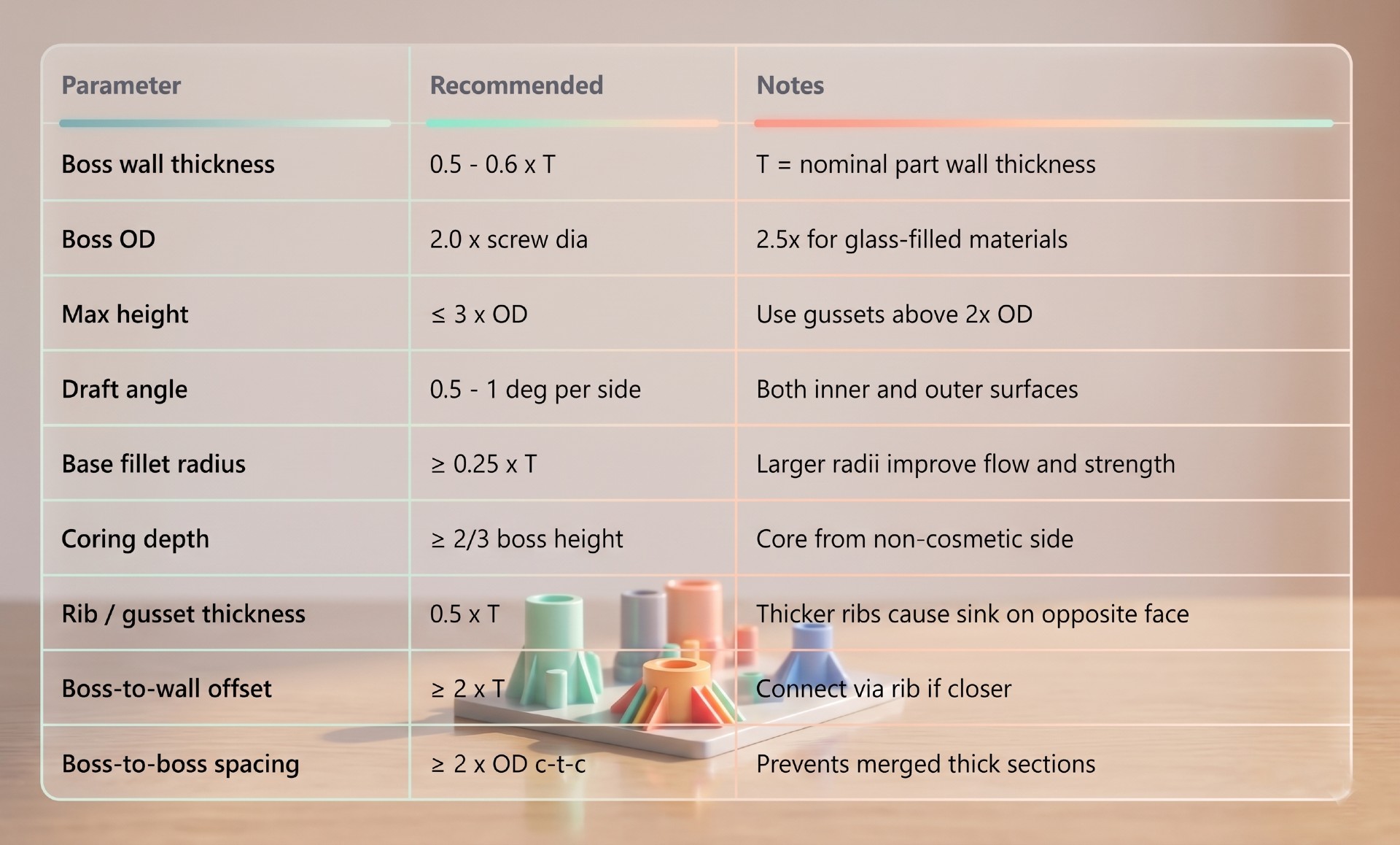
By adhering to the flow dynamics principles of plastic geometry, you can design parts that cool evenly, resist warpage, and exit the mold without a single sink mark in sight.