Eventually, individual plastic components must be fastened together into larger assemblies. The fastening decisions made at this stage, which screw type, which pilot hole, and which insert installation method, directly determine whether your joint survives production, service life, and repeated maintenance cycles. Most failures at this stage are not random. They are geometry.
1. Why Standard Metric Screws Do Not Belong in Plastic Bosses
A common error in product design is driving standard metric machine screws directly into injection-molded plastic bosses. The mechanism of failure is straightforward and consistent: standard metric screws have a 60-degree thread flank angle. When driven into a plastic boss, this wide wedge geometry converts the rotational insertion torque into a large radial outward force hoop stress on the boss wall. Depending on the boss geometry, material ductility, and torque applied, this stress cracks, splits, or shatters the boss.
⚠️ An important precision
The cracking failure is not automatic; it is conditional. A well-designed boss in a ductile material like ABS, with the correct wall thickness and a calibrated torque driver, can survive a metric screw without immediately failing. The problem is that in real production conditions, mixed operators, no torque control, and slight variation in pilot hole diameter, the rate of boss failure with metric screws is high enough to make them a genuinely bad default, not just a suboptimal one.
The failure is almost always a poorly designed boss combined with the wrong screw, not one or the other in isolation. Understanding this matters because it means fixing only the screw selection without reviewing boss geometry solves only half the problem.
The second failure mode of standard metric screws in plastic is subtler but equally important: the "easy" installation feel. A metric screw dropped into an unsized pilot hole goes in fast with minimal resistance — because no thread engagement is happening. The screw is simply displacing unformed plastic until the head seats, at which point all hoop stress concentrates instantly. That ease is not a sign of a good fit. It is a sign that something is about to crack.
The correct rule:
Standard metric machine screws belong only in metallic inserts or pre-tapped metal. They should never be driven directly into a raw plastic boss in a production assembly. If you find yourself reaching for an M3 to go into a plastic boss — stop. That is the wrong tool for the application.
2. Thread-Cutting vs. Thread-Forming Screws
Both types are designed for plastic, but their working mechanisms, material compatibility, and application domains are entirely different. Choosing the wrong one for your material is as consequential as using a metric screw.
Thread-Cutting Screws
Thread-cutting screws feature a slotted shank or fluted cutting point. As they are driven into the pilot hole, the sharp lead threads physically slice into the plastic matrix, severing polymer chains and carving out a mating thread path. The mechanism is identical to a machine tap.
Advantages
Very low installation torque due to cutting rather than displacing material.
Useful where the material cannot deform highly filled composites, such as rigid thermosets.
Disadvantages
The cutting action generates plastic chips and swarf. In sealed electronic enclosures, loose chips can migrate and cause short circuits or foul moving gears. This is a critical and underappreciated failure mode.
Polymer chains are severed; the thread path is weaker than the surrounding material, not stronger.
Application
Thread-cutting screws are reserved for hard, brittle materials where plastic deformation is impossible — rigid thermoset plastics, cast phenolics, or highly filled composites above approximately 50% glass fiber loading. For any ductile thermoplastic, they are the wrong choice. Never use thread-cutting screws in sealed electronics enclosures.
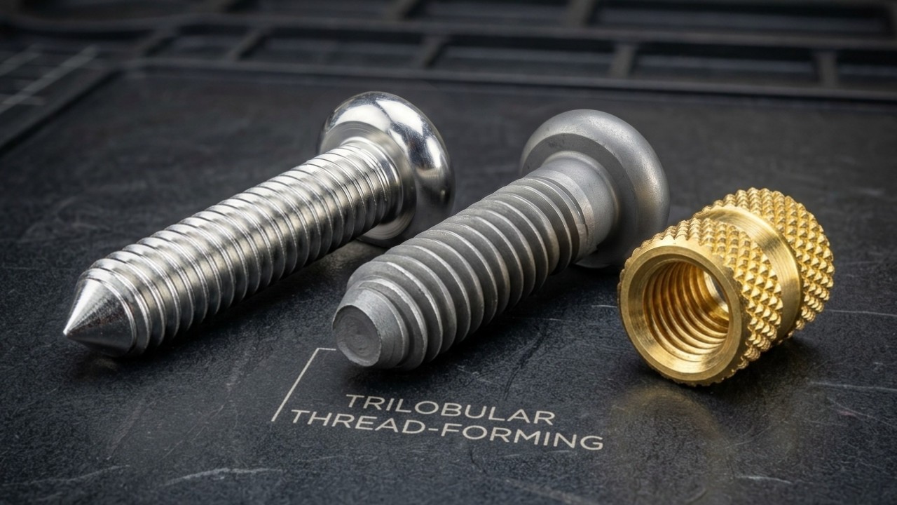
Thread-Forming (Thread-Rolling) Screws
For the vast majority of ductile thermoplastics — ABS, PC, PA6, PA66, and their blends — thread-forming screws are the correct default. These screws do not cut material. They feature a trilobular (three-lobed) cross-section and a narrow 30-to-45-degree thread flank angle.
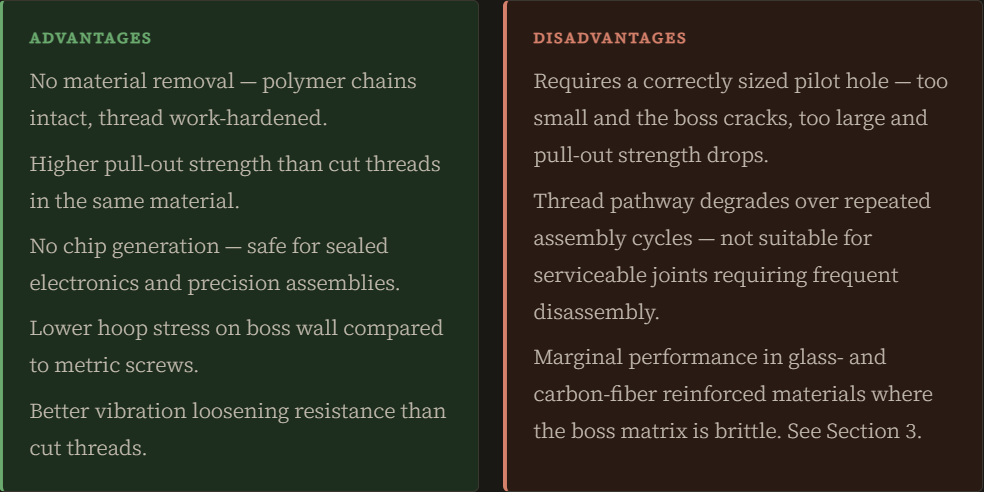
When driven into a correctly sized pilot hole, the trilobular geometry cold-flows and displaces the polymer, forcing the plastic to deform and pack tightly around the root of the screw. Because no material is removed and the polymer chains remain intact, the plastic work-hardens around the thread, producing significantly higher pull-out strength and better resistance to vibration loosening than a cut thread.
The narrow flank angle is the mechanical key. Where a 60-degree metric thread converts torque into radial outward force on the boss wall, a 30-degree thread-forming flank directs the insertion force predominantly along the screw axis. Hoop stress on the boss wall is substantially reduced, allowing more efficient boss wall designs without compromising joint integrity.
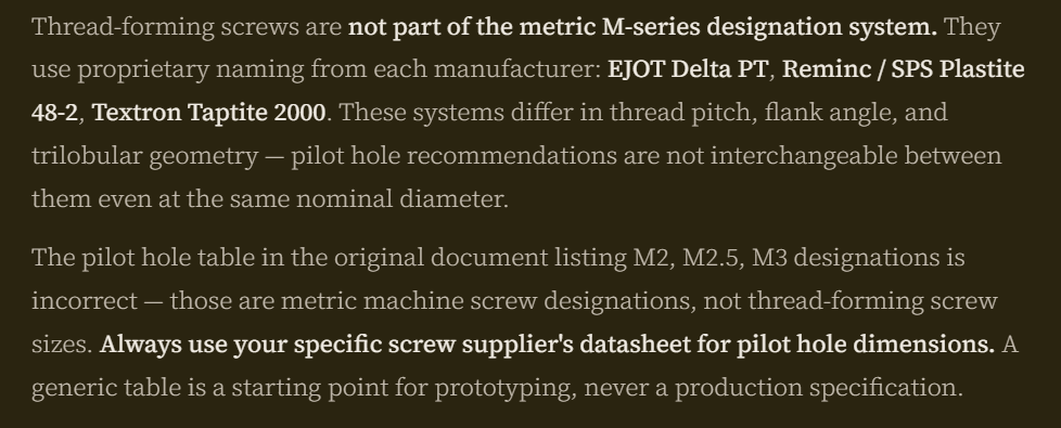
⚠️ Critical designation note — "PT" is not a standard.
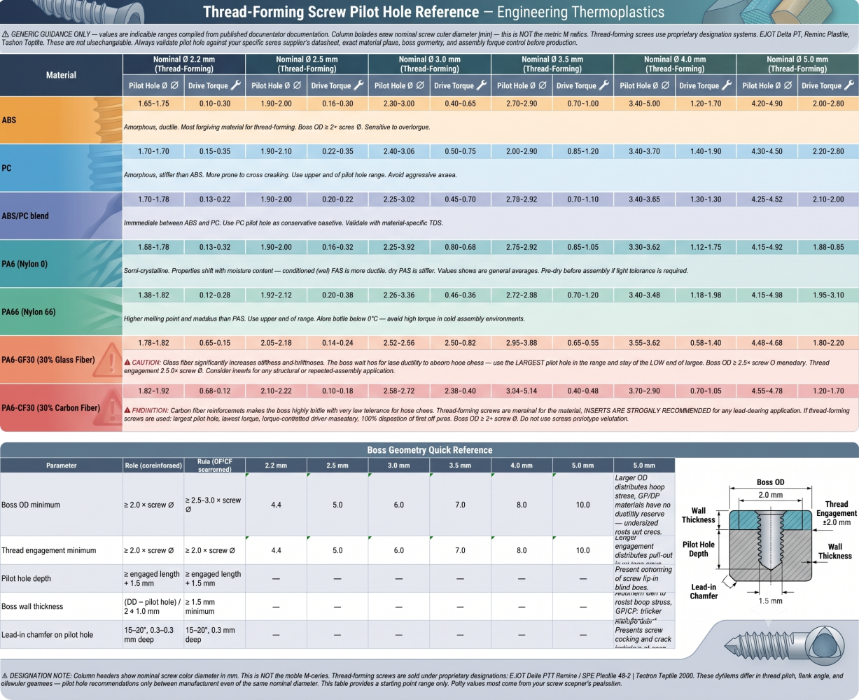
Pilot Hole Reference — Indicative Ranges by Material
The table below shows generic starting-point pilot hole ranges for thread-forming screws by nominal outer diameter and material. These values are indicative only, so validate against your specific screw supplier's published data before committing to production tooling.
💡 Pro-tip: Thread-forming screws are the right choice for non-serviceable assemblies in ductile thermoplastics where the joint will be torque-controlled and assembled a limited number of times. Reserve metallic inserts for joints that require repeated disassembly, carry sustained structural loads, operate in vibration-heavy environments, or are made in glass- or carbon-fiber reinforced materials. The cost difference between a thread-forming screw and an insert installation is real — but so is the cost of field failures and warranty returns from joints that were under-specified.
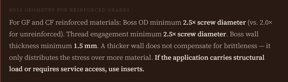
3. Reinforced Materials: When Thread-Forming Screws Become Marginal
Everything described above applies comfortably to unreinforced ductile thermoplastics. When glass or carbon fiber enters the material, the rules change — and the margin for error shrinks considerably.
Glass and carbon fiber reinforce the plastic matrix by restricting polymer chain movement. This is exactly what makes them useful for structural applications — but it also means the boss wall has far less ductility to absorb the hoop stress generated during screw insertion. A PA6-GF30 boss does not deform and recover the way a PA6 boss does. It either holds or it cracks.
For PA6-GF30 (30% glass fiber), thread-forming screws remain viable with careful design: larger pilot holes at the upper end of the range, reduced installation torque, boss OD of at least 2.5 times the screw diameter, and a minimum thread engagement of 2.5 times the screw diameter. The lead-in chamfer on the pilot hole — often omitted as a "minor" detail — becomes mandatory. Any crack initiation at the boss entry propagates rapidly in a glass-filled matrix.
For PA6-CF30 (30% carbon fiber), thread-forming screws are genuinely marginal. The carbon fiber makes the boss significantly more brittle than even GF30, the acceptable torque window is narrow, and any mis-sized pilot hole or slight screw cocking will crack the boss. If you are using PA6-CF30, the practical recommendation is to design for metallic inserts from the start and treat thread-forming screws as a fallback only for non-structural applications with prototype-validated pilot holes and 100% torque-controlled assembly.
4. Metallic Inserts — When and Why They Are Mandatory
Thread-forming screws degrade the plastic thread pathway with each assembly cycle. The first installation work-hardens the thread and produces good pull-out strength. Subsequent removals and reinstallations progressively fatigue the formed thread until it no longer holds adequate clamp load. For products that require periodic disassembly for maintenance, calibration, or repair, this degradation is not acceptable.
Threaded metallic inserts — typically brass, occasionally aluminum or stainless — provide a rigid, metal-to-metal load path that does not degrade over repeated assembly cycles. The fastener threads into the insert, not the plastic. The plastic boss is only ever in compression from the insert's outer geometry — it never sees thread engagement forces directly.
Stress Relaxation vs. Creep — A Necessary Distinction
The original motivation for inserts is often described as "creep resistance." This is partly correct but conflates two distinct polymer behaviours that have different practical implications:
Creep is the ongoing dimensional deformation of a material under constant sustained load. In a bolted plastic joint, you would observe it as the boss itself visibly changing shape over weeks the plastic flowing away from the stress concentration. It is a real phenomenon, but a secondary failure mode in most bolted plastic assemblies.
Stress relaxation is different and more important to understand. It is the loss of clamping force at constant deformation — the joint does not visibly deform, but the polymer molecules internally redistribute the stress over time, and the axial tension holding the joint together gradually dissipates. What you observe is a fastener that felt tight at assembly and vibrates loose weeks later with no visible change to the boss geometry. This is the primary failure mode in bolted plastic joints at room temperature, and it is the reason metallic inserts are mandatory for any joint that must maintain clamp load over time.
Confusing the two leads to the wrong fix. Creep is addressed by limiting compressive stress in the boss wall. Stress relaxation is addressed by removing the plastic from the load path entirely, which is exactly what a metallic insert does.
A bolted plastic joint that feels secure at assembly and vibrates loose over weeks is almost always a stress relaxation failure, not a creep failure. The distinction matters because the remedies differ: stress relaxation is addressed by removing the sustained load from the plastic (via a metallic insert providing the load path), while creep requires limiting the compressive stress in the boss wall. Confusing the two leads to misdiagnosed failures and wrong design fixes.
Metallic inserts address both by removing the plastic from the direct load path entirely. The insert carries the clamp load; the plastic only encapsulates the insert's outer geometry.
5. Insert Installation Methods
Three post-design installation methods exist for threaded inserts. The right choice depends on production volume, material, part geometry, and whether cycle time or joint strength is the primary constraint.
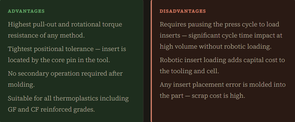
Molded-In Inserts
In insert molding, the knurled metallic insert is placed directly onto a core pin inside the open mold — by a robotic arm or a human operator — before the mold closes. Molten plastic is then injected around the insert at full injection pressure. As the plastic cools and shrinks, it encapsulates the insert's external knurling completely, producing the highest achievable pull-out and torque resistance of any installation method.
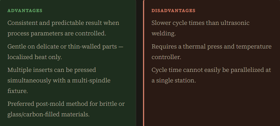
Heat Staking
A heated thermal press pushes the metallic insert into a slightly undersized molded hole. Localized heat melts the plastic boundary layer at the interface, allowing it to flow into the insert's knurling. On cooling, the encapsulated knurling locks the insert permanently in place.
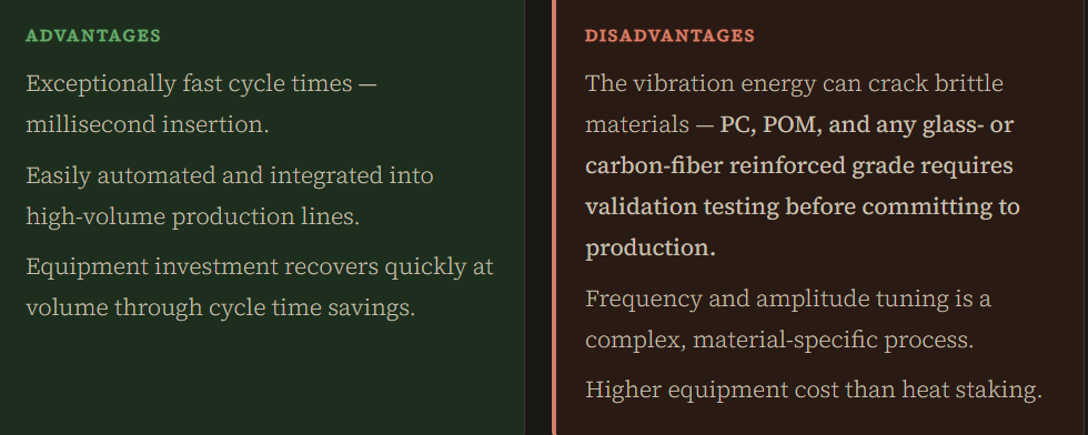
Ultrasonic Welding
An ultrasonic horn applies high-frequency mechanical vibration to the insert while pressing it into the molded hole. The friction generated at the plastic–insert interface melts the plastic in milliseconds, seating the insert at speed.
Choosing between the three methods:
- Molded-in: Maximum joint strength, precision positioning, low-to-medium volume, or when the insert location is structurally critical.
- Heat staking: Medium-to-high volume, brittle or filled materials, multiple inserts per part, or when ultrasonic vibration is a cracking risk.
- Ultrasonic welding: High volume automated lines, ductile unreinforced thermoplastics, cycle time is the primary constraint. Always validate on glass- and carbon-filled grades before production commitment.
Key Takeaways
Fastening injection-molded plastic is not a detail to resolve at the end of the design phase. The screw type, pilot hole, boss geometry, and insert method together determine whether your assembly survives the first torquing, the first maintenance cycle, and two years of service vibration.
The hierarchy is simple. Thread-forming screws — not metric, not thread-cutting — are the correct starting point for ductile thermoplastics in non-serviceable assemblies. Metallic inserts are mandatory for serviceable joints, sustained structural loads, vibration environments, and reinforced materials at or above 30% fiber loading. And for every application, the pilot hole comes from the screw supplier's datasheet — not a generic table with metric designations on it.
Get the geometry right before the mold is cut. A boss wall that is 0.3 mm too thin costs nothing to fix on the CAD screen and an entire production run to fix in the field.